Tampilkan postingan dengan label up. Tampilkan semua postingan

Selasa, 05 Juli 2016

Sneaking up on Perfection

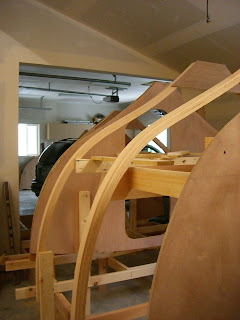
For the first time in my short design-build career, I am finally in the stage I have longed for, that is, to be working on mk II and mk III+ versions of already successful boat models. Thus the blog title, "Sneaking up on Perfection". This is certainly the case with the Echo Bay Dory Skiff (EBDS), my first kit, based on a design a friend had drawn 26 year ago. Ive built many Echo Bays with families, corporate teams, and students. When it came time to start the kit business, it was obvious to begin with the EBDS. At that time, I had no idea how powerful 3D modeling programs could be and it didnt matter, I was a long way from knowing how to draw a line segment in 2-dimensions!

The original Echo Bay (left) at 26 years old and the mkIII version as a kit (right). 

The EBDS is the last of my boats to get modeled in the computer. After a couple weeks of side-work, I have just finished the new model. The improvements are:

  • improved sheer for aesthetics and sailing purposes
  • slightly longer (now 11 10" LOA)
  • increased freeboard (about 1")
  • more interior options: enclosed plywood tanks for flotation and 2 different solid-wood thwart arrangements.
  • improved sprit sail shape and new lug rig option
  • dedicated oar plan for the EBDS
  • paper plans will be available as well as full size patterns (FSPs) and a plywood kit
The new lug rigged option

Next step is to break the model apart and develop the 2D geometry. Ill start by unrolling the planks and flattening the bulkheads, frames, and other hull structure. This process of generating 2D geometry takes very little time (maybe 2-3 hours). The time consuming part is drawing the plans for how to make these parts from scratch and drafting the construction drawings so she can be built as designed. This will take another couple weeks of side work. Then the CAD files for cutting on a CNC machine will need to be made, another couple days of side work. 

This model shows the standard solid wood thwart arrangement, but a plywood (flotation) tank option is a new addition.


Phew. A lot for a 12-footer. But on par for creating what will be the best 12-foot sail and oar skiff the market has seen for a long time, perhaps ever! But this photo shows why I do it: adventures with the kids.
A recent outing in the EBDS with the skipper (the one in the stern).


Read More..

Rabu, 01 Juni 2016

Up Date on Seating Positions in Dinghies

Rick has written an excellent comment about the previous post - please take the time to look at it, as the idea is very good indeed. I have thought of a similar system, but Ricks is the best idea yet.

Having sailed in a few small boats myself, I concur very strongly with Ross regarding side benches. If the seaway gets a bit active, they get in the way very quickly. If one really MUST have them, they should always be removable, but latched down with buttons so they dont come loose when things get really rough, as sooner or later they will if you sail much.

As for me, same as Ross; sitting low in the bottom of the boat with back against the coaming, or sitting on the windward washboard (side deck) is the way to sail a small boat.

For sleeping with a decent amount of dry, level room in a small open boat, one you wont roll off of, why not build in a pair of risers just above the height of the thwart and the sternsheets, with buttons on the backside of each, facing outward to the hulls planking? Then when you want to sleep aboard, you unroll your strong canvas trampoline, slip its grommets over the buttons, stretching it between the risers, and sleep on that up out of bilgewater and high enough above the thwart and sternsheets to avoid hard corners in your back. On some boats that might create a space wide enough for two to sleep.

No need for the obstruction of side benches at all, and the risers, if made a bit wide in their vertical plane and thought out carefully, notched into half frames, should make a good backrest supplementing the coaming or washboard carlin each side. Adds a bit of weight, but Ill wager that itll be a lot less than the side benches, with no obstruction of internal space and no loose hunks of wood coming loose on you at the worst possible time.


Also, Geoff Leedham has emailed me to say that there is no obvious support for the seats when in the centre location. The cleats for the centre location hadnt been installed at the time the photos of the seats in the "side seat" location were taken. However, in the shot where you can see the seats butted together in the centre "sleeping flat" position, there are 19mm x 19mm (3/4" x 3/4") cleats screwed to the forward face of the stern sheets, and to the aft face of the main thwart. Look at this photo and you can see the outer cleats - there are similar ones under the "sleeping flat" set-up on the centreline. It is a very simple arrangement.

Read More..

Minggu, 22 Mei 2016

Setting up the Strongback

Unfortunately we didnt take any photos of the laminating of the frames or the cutting of the bulkheads from marine plywood. This took roughly 100hrs, and the majority of January, 2009. Richard started keeping track of actual hours and what was accomplished on a "Wooden Boat" calender he received for Christmas. This has been very useful since I am writing this after such a long delay.

February was taken up with gluing approximately one to two half frames each day, as a large amount of the lofting table was taken up during the clamping and drying.

In March, it was time to start setting up the strongback. This is the rectangular frame made of 2x12 lumber, attached to the floor. It will support her and hold everything rigid during the building process.


Extensive bracing is required so that there is no movement of any of the parts. The bulkheads have to be in the correct location since they will become fixed to the hull during the stripping. There was lots of head scratching, interpretation, and double checking of the plans.


A plumb-bob and the DWL (water line) marked on each piece were used to help find the appropriate location of each piece.


Many of the bulkheads were only partial pieces (partitions), and will create the beginnings of interior walls and furniture when she is rolled. Bracing had to hold these structural pieces in mid air, so some of the braces needed to be redone as parts were added. And of course, this is all done upside down so port and starboard can get rather confusing.

The doorway seen below will be the entry into the forward storage/ head area, and sits just forward of where the mast will be.

The small triangles of plywood joining the rib frames at the top will become the supports for the floor.
Braces start appearing at every angle, and numerous minute movements of a bulkhead "just a quarter inch this way or that" ensues. Since Richard has no experience with how any little error in position may develop into a major hassle down the line, perfection is mandatory.
Her bow protrudes into the true garage area, and doesnt have the stem attached yet. The stem is the curved piece that will be laminated up to create the shape of her bow, again from the off sets, and by scaling off the plans.
And the black dog starts to doubt if it will ever squeeze out of the side room of the garage...
thats an 86" wide door and a 10 foot high beam.
Read More..

Kamis, 21 April 2016

Folding Mast Hollow Sixteen Sided will end up round

In Woodenboat Magazine #237 of March/April 2014, there is an article written by David McCulloch about building an "In-Mast Hinge" which he has designed and developed. I urge you to purchase a digital issue of this copy if you dont already have it, as Mr. McCulloch has written a good article, and there is an excellent coloured illustration.

 https://www.woodenboatstore.com/product/WoodenBoat-magazine-issue-237-march-april-2014-DIGITAL

David McCollough"s photograph of his "In-Mast Hinge" from the Woodenboat Magazine article. Note the detail in the upper-right corner.
This article inspired a customer of mine to inquire about including such a hinge in a replacement mast for a large, open daysailer he had recently purchased. After some discussion, and an inspection of the boat, I agreed to attempt the project. It was necessary for me to make modified drawings for the plates to fit the mast I was commissioned to build due to its different diameter from that shown in the article.

The location of pivot holes, and the radii of cuts made to all three plates alter depending on the geometry, which is itself dependent on the diameter of the mast. However, this is not at all difficult to work out, and just requires attention to detail.  For those who may be interested, here are some early progress photos: -

One half of the mast being laid up in a female station mould mounted on part of my 12 metre (40 ft)-long bench. The mast is made up of 16 staves, so this half-shell comes from 8 tapered pieces.

All eight staves glued up in the female mould. The first stave was fixed along a marked centreline in the bottom of the female stations, using 18 gauge polymer brads fired from a pneumatic branding gun through the stave and into the plywood edge of the station mould. Subsequent staves were laid up on either side of the "master" and glued using epoxy. The overwhelming reason for using epoxy is that it only requires contact pressure to form a good bond. Careful attention must be paid to priming the gluing surfaces with un-thickened epoxy before applying the thickened mixture. This method allowed me to fire polymer brads into the SIDES of each successive stave to hold it to the one before, because the epoxy did not require clamping pressure. The polymer brads stay inside the shell of the mast, and will of course never corrode. The bradder and polymer nails were purchased from Duckworks. After being glued-up, the inside of the half-shell was given three or four full coats of epoxy to ensure that the inside of the finished mast would always be protected from moisture.

Here is the station mould after the removal of the first mast half-shell. I used adhesive tape applied to the inside  of the cut-out section of each mould to prevent epoxy squeeze-out gluing the mast components into the mould. Alignment of moulds is very important, and you can see the blue chalk-line "snapped" onto the bench surface (now covered with epoxy drips!)

Two half-shells of the mast after being removed from the station mould visible in the top/right of the photo. The outer surfaces are still rough-looking due to epoxy marks. When first removed from the mould, the half-shells had lots of thickened epoxy squeeze out, which I largely removed using a heat-gun and scraper. Any gaps were filled with additional epoxy.

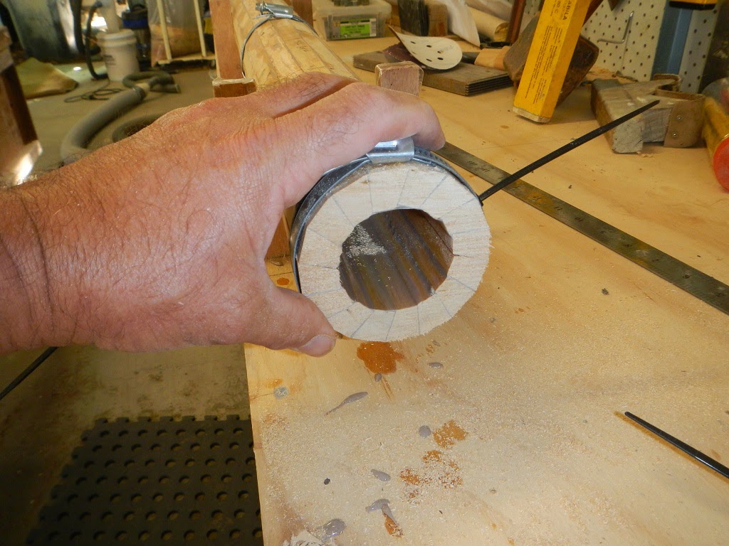
Here you can see the two shells clamped together with cable-ties and hose-clamps. The extra length of the staves has been roughly cut off using a handsaw and you may just be able to see that there is no glue on the opposing faces of the two shells. Note the heavy layer of sealing epoxy on the inside of the hollow mast.

This is a similar photo, but taken from the mast head. The trimming of the extra length  was done quite roughly, and the un-glued faces of the staves still need to be sanded to remove dags of cured epoxy, so the gaps in the un-glued faces are a bit open. This will change prior to final assembly. Note that the taper of the mast resulted in a reduced outside diameter, but the thickness of the staves has reduced as well. The idea is to keep the percentage wall thickness of the mast constant at about 20% of the diameter. This is something which cant normally be done with a "Birds Mouth" mast. (see photo below)  
An off-cut from the tip of  "Birds Mouth" mast I made. a while ago. Note how the wall thickness, which started off at the base being 17% of the diameter, has ended up being so large it almost makes the mast solid.  Compare with the previous photograph.

Three stainless steel plates to make up the hinged section of the mast (refer to the inset in the David McCulloch photo at the beginning of this post to see how this works). These plates are quite heavy, with the outer pair being 6mm thick, and the inner one being 8mm. I had these laser-cut, which saved a lot of time, and was not expensive.
This sketch shows the stainless steel plates extended and folded. The black lines depict the 8mm plate which is buried for half of its length into a solid mast stub which runs from a mast step near the keel to a short distance above the deckline of the boat. The red lines show the two 6mm stainless steel plates, which are fully buried in the base of the mast you can see in this article.
Here is a close-up of the insert from the heading photo in David McCullochs article in Woodenboat Magazine #237.
 https://www.woodenboatstore.com/product/WoodenBoat-magazine-issue-237-march-april-2014-DIGITAL 

There needs to be a solid section at the base to hold the stainless plates. On the free-standing hollow masts which I normally make, I always insert a solid section from the base of the mast, to a reasonable distance above the mast partners. In both my normal free-standing mast inserts, and with this one, I terminate the solid insert with what is often referred to as a "Swallow Tail", the purpose of which is to ease the transition in stiffness from where the mast is solid (i.e. the hollow shell combined with the solid inset) to where it is a hollow shell. Here is a view of the early stages of the solid insert for this mast.

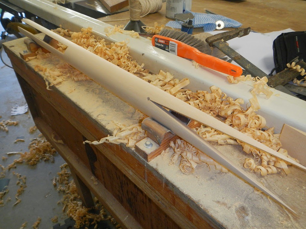
As you can see, there is the "Swallow Tail" section, and at the base, a cut-out slot to accept the stainless steel plates and an 8mm hardwood inset to hold them apart and allow the 8mm tongue of stainless from the mast stub to fit between. At this point I have planed a square blank into an octagonal section - it is on its way to becoming round!
At this point the blank has been planed from octagonal, to 16-sided, and them planed further to 32-sided, and then hand sanded to a round cross-section.. All of this sounds complicated and difficult, but if you start with an accurately cut square blank, and then mark carefully for the 8, to 16, to 32-sided planing work, youll find that the work goes quickly, and is actually a satisfying and relaxing job. As with most boatbuilding work, it just a progression of simple steps. I can tell you Im finding it more difficult to describe than it is to achieve on the bench. Other than the initial sawing of the square blank, I did all of this with a low-angle block-plane you can see in the photo before this one. It did not take long.

The hole you can see drilled through the filler block at the apex of the "Swallow Tail" is just something I do to prevent a crack propagating from the apex. This may be an over-kill, as the block will be contained within the mast shell anyway, but it only took a moment to drill - so better to be safe than sorry... 

Here is where the stainless steel plate assembly will eventually reside. Matching slots will have to be cut in the mast shells.


Checking the fit of the insert. The actual fitting will be done with the two half-shells of the mast opened up, and the plug will be laid into a bed of epoxy in one half, before the pair of shells are finally glued together to form a round, tapered mast. The tip of the mast will receive a similar (but smaller) plug to distribute loads from the shrouds and fore-stay, and to carry the attachments for the halyard blocks
Ill write more about this interesting folding mast experiment as the job progresses.


Read More..

Sabtu, 02 April 2016

Daves musings about setting up and adjusting sails on R C model Boat

Dry sailing -set up.

Place the model in a stand. Head the model into them wind.

Things that can be moved, and adjusted: Mast step. Mast rake. Boom vangs. Shrouds. stays. Jumper stays. Head stay/jib stay. Sail shape - loose foot. out-hauls.

Attach the sails to the mast.

Set the sail winches in fully trimmed position while allowing sheets to be slack.

Stand the mast with standing rigging attached in the center step position.

Hook the jib swivel into the middle slot of the jib rack. {The jib boom needs to clear the mast.}

Connect the side stays to the chain plates and adjust so the mast is straight and vertical.

Connect the back stay to the back stay fitting.
The jib stay and back stay will need adjusting to set the mast in vertical position.

Move the out-haul of the sails along the boom to give the sails to have some "belly". Pulling the sails out along the boom flattens their shape. The belly (or shape) of the sails will be determined later and the sail shape will be determined by how windy it is.

Where you attach the sheets to the booms will take into account the type and adjustments available for the sail control. The booms should be full out (90 degrees to the center line of the hull) when the SCU is full out and then the booms should be just about over the center line when fully trimmed in. ( I see 10 degrees as suggested angle to center line). The length of jib sheet trimmed and the length of main sheet trimmed is a factor in setting up the sail control so the sails are coordinated properly when sailing. The SCU handles a much longer main sheet than the jib sheet. The use of jib traveler and mainsheet traveler can help position the sails when fully trimmed in. Unless two servos (SCUs) are used a single SCU has the task of coordinating the positioning of the jib and main.

Turn on the R/C and run the SCU.
Test out SCU setting with the sails full out and fully trimmed.

With the mast set up and sails adjusted roughly in position it time to launch and sail.
--
Setting Sail on the water.

Before launching TURN on the radio on the boat. I have seen many models set loose to sail with the on board receiver and sail controls not tuned on and very unhappy skippers watching as their model sails away towards the horizon.

The initial rigging and sail settings are based in getting the model to sail a strait line while close hauled (sails trimmed in) and sailing up-wind.

Properly trimmed the rig will allow the model to sail it self in a straight line with just a minor tendency to "round-up" (i.e. sail itself dead into the wind). If or example you find you are constantly pulling the tiller (i.e. rudder) hard over to pull the model back on course to keep from heading in to the wind your model has weather helm which means your mast and jib must be re-positioned. When tacking if your model stalls into the wind and wont tack? Try different rig setting.

--
Setting Sails
The art of tuning the rig on a sail boat is detailed in books written for racing yachts and boats.

"DINGHY SAILS"
by Jeremy. Howard-Williams

"The Best of Sail Trim:
A Selection of Articles from Sail Magazine"

"Sail Trim: Theory And Practice"
by Peter Hahne

My observations and commentary on tuning are from an amateur and are at best suggestions not professional advice.

Observation Number One!!
Model sails that are single panel loose footed sails rely on the shape of the sail established by the gap between the boom and the foot of the sail. Model sails with "shape" sewn into the sail fabric still are loose footed. Also the lift of the boom also factors in determining the shape and performance of the sails.

Hauling a sail into the center line and at the same time pulling down on the sail can flatten the fabric and kill the sail shape. I like to use travelers to position the sail to the desired point near the center line. Then you can set the point of maximum driving force and not wreck the sail shape.

On a big boat the skipper can changer the suit of sails to match the cut of the sail with the wind conditions. In the case of a model a skipper can change where the out-haul is along the boom, light air adding belly to increase the drive, heavy air pulling the sail out further changing the sails airfoil.

The jib and mainsail work as a system. A skipper has all manner of combinations that may be set relating the two sails. If the models did not have jib clubs they could overlap the mainsail. So model sailors have to adjust the "slot" between the jib and the main to get the maximum driving combined air foil.

In heavy air you may want to close the slot and ease the main so that the jib slightly back-winds the main to help the model sail flatter (less heeling).

Dont forget on a model it is easy to rake the mast fore and aft to trim the sailing characteristics to match wind conditions.
--
A digital camera can be a terrific diagnostic tool for seeing what is happening on your model. You can look at pictures and spot misadjustments. Bends in mast, wrinkles in sails etc. Does you models mast rake forward down wind? Is the back stay bending the top of the mast. How are the jumper/jenny stays adjusted do they balance the tensions between the jib and the back stay?
--
The late Manny Costa of RI always stressed, change one thing at a time to see what changes. He also stressed sailing a pair of models. One model being tuned and sailing against the second to see if the single adjustment improved performance.

Round-Robin racing in pairs is an excellent way to evaluate how your model performs.
Read More..

Jumat, 25 Maret 2016

Catching Up on Some Comments

For quite a long time now Ive been unable to up-load photos to my blog without going through the process of putting them on a picture hosting site and them using the url of each individual photo. With the combination of Christmas/New Year, and a lot of building work to be done, I am afraid that posting has fallen behind. This is all done in my own time, and at my own expense, and it sometimes must take second place to paying work!

The computer people here will roll their eyes, but Ive finally discovered that the picture loading problem was caused by incompatibility between the Microsoft Internet Explorer I had been using and the Google Blogger program which I use for the blog. Ive now changed to Google Chrome for my internet work, and all seems to be working fine.

So Im going to start off by answering a few comments that have been left on some of my posts.

Mr.Lillistone,Ive followed your blog for a while,Thank you for your time,energy ,and expertise,It is appreciated by many!!! I know you have built both Michalaks Mayfly and Redmonds Bluegill,Im considering building either one and would like your professional opinion.Do you think the Mayfly leeboard and balanced lug sail plan could be used on the Bluegill ,if the sail is properly positioned over the leeboard,and leeboard is centered on beam?I would like the open cockpit the leeboard affords.Any info. Would be appreciated thanks in advance ! Jerry Fehn on Reality

The Bluegill we built, showing her centreboard case
Jerrys comment refers to a matter which has nagged at me for many decades. A centreboard is convenient to use and is to a large extent self-tending i.e. put it down and if you are too busy for detail work, just leave it down until it hits the bottom coming home. On the other hand, leeboards need to be handled from tack to tack because, as their name suggests, they only work when set on the leeward side of the boat.

A raised leeboard on a Dutch Yacht (taken from http://www.leeboards.com/)
That is me sailing my Bolger Nymph a long time ago. I had fitted her with leeboard for experimental purposes, but in this photo they are both raised as the boat is running downwind.
My understanding is that leeboards originated in China, along with such things as stern-mounted rudders, centreboards, and watertight bulkheads to name just a few Chinese nautical inventions/developments. Leeboard use has been widespread, but most people associate them with Dutch, German, and British sailing vessels.

This shows a typical lowed position for a leeboard.

Leeboards may appear untidy to some eyes, and to need handling from tack to tack, but they are highly efficient. Frequently the boards are angled away from the hull to allow a clean passage of water between the hull and the board so as to prevent excessive drag. This feature also means that as the boat heels, the board becomes more and more vertical - which is just the opposite of what happens with a centreboard or fixed keel. Not only does the board become more vertical, but it also works from the surface of the water, whereas the centreboard only works from where it exits the bottom of the boat. This has the additional benefit of allowing leeboards to operate effectively in a partially raised position in shallow water, and not extend below the bottom of the boat.

A Bolger Black Skimmer sailing with her board partially raised. The board is effective, but does not extend any deeper than the hull, if at all. (Photo from Woodenboat Magazine)
An overlooked plus with leeboards is that because they each operate operate on different sides of the boat (in their normal form anyway - more on that later) the sectional shape of the boards can be asymmetrical, allowing the board to lift the boat to windward at a reduced angle-of-attack in comparison with a board which has a symmetrical foil shape. The boards should have a flat face away from the boat and a cambered face towards the boat.


An Otter II with both of her leeboards raised while on her shallow water mooring. Note how the owner has the leeboards on the incorrect sides. The cambered section should face the hull, so in this case the starboard board is mounted on the port side, and the port board is mounted on the starboard side!
You may wonder why leeboards frequently have a tear-drop or triangular shape, with the widest part down low. This is because they are surface-piercing foils, and the inverted taper shape helps to reduce air-ingestion  on the low-pressure side of the board.

Despite the visual and actual clutter of the boards, they have some potent advantages in addition to the ones already mentioned: -

  • the interior of the boat is totally free of the intrusion of a centreboard case; and
  • the bottom of the boat is stronger without a centreboard slot; and
  • there is no centreboard slot to get jambed up with mud, stones, shell grit and sand - which therefore leads to the centreboard being jambed.
It is possible to mount the leeboard to one side of the boat only, but for that to be effective, the board must be prevented from bending away from the side of the hull when it is on the up-wind side. This can be done using a dagger leeboard ( which I guess would be a weatherboard on one tack) where a variety of methods are used to hold the board in place. Alternatively, you can have a pivoting lee board as developed by Jim Michalak and others. In this case, the board is held parallel to the side of the boat by a pivot bolt and wooden guards and/or slots, but the board is free to pivot in the vertical plane. Although simple in concept, great care is required to ensure that all of the pivot locations and guard angles are absolutely correct.


Above two photos show the Michalak Mayfly 14 pivoting leeboard
Here is the finished boat
Note the completely unobstructed interior....
...the very simple raising and lowering gear...
...and the lower guard with the pivot bolt going through (the piece of unpainted wood is positioning piece on the trailer)
Now, to finally get to Jerry Fehns question - Yes, it would be possible to mount a pivoting leeboard on Bluegill in place of the centreboard and case, but great care needs to be taken with the positioning of the board relative to the centre-of-area of the sail, and also with the geometry of the pivot point and the guards so that the board remains parallel with the centreline of the boat.

Having said all that, the first person who should be consulted would be Steve Redmond, the designer of Bluegill. As has been said many times in the past, no-one should alter the design of a boat without getting input from the original designer. This is not grandstanding at all - it is simply that the designer should have put a lot of thought into the design, and there may be elements there which are not obvious to the casual observer.

My recommendation would be to build something like Mayfly 14 if sailing is the most important aspect of operation. She sails superbly in my experience, and the shape of the hull is optimised for sailing whereas Bluegills hull is a deliberate attempt to produce a hull that will row, sail, and operate as a planing powerboat.
Read More..

Jumat, 11 Maret 2016

Balance Lugsail Setting up a Downhaul

One of the great pleasures associated with owning a home-built, traditionally-rigged boat is that you can fiddler around with the running rigging for years and years. My old boat is forty years old and Im still altering details of the rig. It is educational, fulfilling, and wholesome activity!

My old boat running home in 30 knots of wind, with the main reefed. Everything in the rig, with the exception of the sail, is homemade and home-designed.

Here are some photos which illustrate the downhaul arrangement that Paul Hernes has developed for his Phoenix III. Control of the downhaul is critically important in getting good performance from a lugsail, and this arrangement allows the downhaul tension to be controlled by a single-hander in a very simple fashion. Additionally, this downhaul is also used to tension the snotter when Paul is using the larger spritsail, so one piece of simple equipment does two separate jobs - and does them both efficiently.

Here you can see the four-part downhaul made up of common polyester braid and two cheap stainless steel vang blocks. Note how the tackle is attached to the rugged mast partner, and the running end passes down through the mast partner........
...and on down to a turning block set low in the boat.
From there, the downhaul leads aft through a hole in the semi-bulkhead and along the centreboard case bed-logs.......
....and terminates in a cam-cleat on the aft end of the centreboard case. This is within easy reach of the skipper and can be tightened or released in a matter of seconds.
This picture shows the simple attachment to the boom. Paul has used a very strong-but-light piece of Dyneema (or Spectra) but for a short length like this anything would do, as stretch would not be an issue. The attachment to the boom can be a loop (as here) or a rolling hitch. The important point is that the attachment can be moved forward or aft along the boom at will, allowing wonderful adjustment of luff and leech tension.
In Pauls arrangement shown in the photos, the boom is simply held close to the mast by the tension of the downhaul. However, there are plenty of other options - in the above drawing is one that I favour as it holds the boom securely against the mast and also allows one to adjust the forward and aft location of the boom with ease.
 I encourage everybody to read widely and to experiment with all sorts of rigging options. If you are not constrained by the rules associated with a racing class, go out and have some fun with homemade equipment - it is cheap, and if you made it yourself you can obviously fix it as well. Usually all you need is some line and a few bits of timber - and your brain!
Read More..

Kamis, 10 Maret 2016

Following up on some comments

In relation to my post, "Lugsail Performance - Better than you may Imagine", Simeon writes: -


I know youve been busy with First Mate but some of us fans are still waiting for illumination on your comment from an earlier blog entry:

"In a later post Ill show you how you can improve the windward performance of the lugsail even more, using nothing more than a short length of V.B. cord."


Well, I have been very lax both in the writing of posts, and in the answering of comments. Im sorry for that - it has been a combination of building a house, trying to catch-up of long overdue work (and in the process, putting food on the table), and having more plumbing work done on my heart (currently up to nine stents). Still, it is not an excuse for me being rude and dismissive.

Regarding the method of improving the performance of a lugsail when sailing on the wind, a clue lies in the sheeting arrangement on a Chinese lugsail.


My old boat, which is still sailing after 45 years, here sporting her Chinese Lugsail back in about 1990


The system I use to improve the performance of a lugsail is a very simple vang which which leads to the head of the yard. This vang system can also be used effectively with all varieties of lugsail (balance, standing, and dipping), the sprit rig, and the gaff-headed rigs of differing styles.
 

Most people are familiar with boom-vangs, but the vang Im showing here operates at the top of the sail, and unlike boom-vangs, it is very lightly loaded, requiring only a light line. This is not an idea of mine - vangs like this have been in use so centuries - however, I suspect that my method of rigging and adjustment is novel.
 

In the above drawing, Ive shown a small boat with a balance lugsail set close-hauled. For the sake of clarity, I have omitted the mainsheet from the sketch.

The vang is simply a length of 3mm (1/8") VB-cord made fast to the head of the yard. In the case of a sprit rig the vang attaches to the upper end of the sprit, or to the outer end of the gaff for a gaff-headed rig.

I have drawn the vang in red, and it runs down to a thumb cleat on the weather side of the transom, across to a simple fairlead on the rudder head, and then along the tiller to a small V-Jamb cleat or a little cam cleat located in a convenient position to allow adjustment. There is very little load on the vang, and it is quick and easy to adjust.


The vang is lead to the weather side so that the angle it makes up high is not too acute, therefore increasing the mechanical advantage. When tacking there is no handling required, because the vang slips out from under the thumb cleat of its own accord as the sail moves across the boat. After the tack has been completed and the boat has settled on the new course, it is a simple matter for the skipper to reach over and grab the vang as it blows out in a smooth curve from head of the sail down to the rudder, and slip it under the thumb cleat on what has become the new weather side of the transom.


For up-wind sailing, this simple vang allows one to adjust the amount of twist in the sail from boom to yard (or gaff, or sprit), greatly improving performance if the crew knows what they are doing. Some will tell you that you should have twist in a sail to take into account "wind gradient". Well, full-size empirical testing has shown that such a thing may be of value at very low wind speeds, but once the wind speed exceeds 6 knots, you are better off with minimum twist.


Sailing downwind, the very same vang can be used to prevent the yard/sprit/vang from going beyond 90 degrees to the centreline of the hull (70 or 80 degrees is better), therefore avoiding the dreaded "death roll".


In this photo of Phoenix III at rest, you can just make out the 1/8"/3mm vang blowing out in the breeze behind the sail. Obviously it has been completely loosened off, but it gives an idea.

Read More..