Tampilkan postingan dengan label progress. Tampilkan semua postingan

Senin, 18 Juli 2016

Website and Blog Making Progress Slowly but with Determination!

Those of you who have been patient enough to be checking back to see how progress is going on the new website and the blog deserve an explanation about what is happening.

Due to an excess of work and looming deadlines, Ive been caught between devoting time to the workshop and to development of the new website and the blog. Jobs in the workshop are well in hand (and must take priority), but by September my contracted work will be complete, and Ill then be turning my attention to fun jobs in the workshop, and lots more writing and design work. With good luck and sensible management, this should result in lots more articles and the publication of a stack of designs I have sitting in the wings waiting for finishing touches. Yes, I know you may have heard me say such things before, but I really am ploughing through the work at the moment, and I have for many months now had a moratorium on taking on any new building/repair work.

Tomorrow Ill post some photos of recent work, and a list of current jobs. One particularly interesting project is the building of a sixteen-sided mast for a large sailing dinghy. This mast is unusual in that it is not only hollow, but the wall thickness tapers as the mast tapers, so the wall-thickness as a percentage of mast diameter remains constant. Another interesting feature of this mast is that it incorporates an in-mast hinge - sort of like a tabernacle without a tabernacle (see Woodenboat Magazine #237 for the idea)
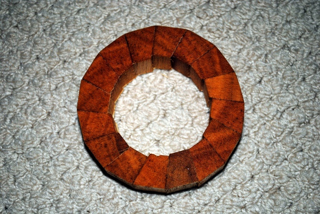
Here is a slice off a test section of my mast construction method. There is a very good reason for the angle being cut into one side of each stave, rather than half the angle being taken of each side as they used to do it in the old days. Maybe I tell you why some day...
The sixteen-sided method is probably too labour-intensive to be practical without a production set-up, but the experiment has provided me with valuable insights, and has been R&D time well spent. Maybe eight-sided next time? The method does have advantages over the Birds Mouth method, mainly in providing the ability to taper wall thickness as well as diameter - all in a home workshop.

Im just beginning to come to grips with some of the complexities of the website program and associated plug-ins, so there will be gradual (but accelerating) addition of content and pages. Further down the track will come video tutorials on some interesting stuff.

Facebook and Twitter have me somewhat stumped at the moment, but that will improve with time - especially after workshop commitments are complete.
Read More..

Jumat, 24 Juni 2016

First Mate Progress

As some of you may know, I have a First Mate under construction in my shed. I started her a number of years ago, with the aim of testing the panel developments for the design prior to releasing the plans for sale.


The significance of the need for testing when dealing with developed panel shapes in a stitch-and-glue design is that it is the size and layout of the hull panels which determines the three-dimensional shape of the finished hull rather than relying on an internal skeleton which has been carefully plumbed and shaped, and around which planking is laid.

One is built from the outside-in and the other is built from the inside-out.

Here is a carefully set-up hull on a strongback showing the stem, internal keel (or maybe keelson) and a large number of transverse molds around which the planking will be laid. In this case the internal structure determines the shape that the planking will adopt.

In this photo you can see the bottom panel of First Mate having the bilge panels attached using cable ties. The boat is already taking up a three-dimensional shape without any internal framework to help. This system relies totally on the accurate design, marking and cutting of the panel shapes.
This is the very same hull in a photo taken about ten minutes later. The topside panels have been attached with a small number of cable ties and the final shape of the hull has already been defined.

The fundamental difference between stitch-and-glue and any other sort of construction (with the possible exception of Birch Bark canoe building and some forms of Scandinavian "built by eye" lapstrake (clinker) building) is that it is the shape of the cut hull panels that determine the shape of the assembled hull, rather than the rigid internal skeleton as with a conventional boat.

Im not saying for one moment that one system is any better than another, but rather I am trying to illustrate why it is so critically important that stitch-and-glue hull panels be absolutely correct in their shape.

Hull panels for a scale model of Three Brothers showing how different the flat panel shapes are......

......compared with when the panels are assembled.
 Anyway, to get back to the First Mate that Im building, once the panel shapes were proven? to be correct, there was no urgency in finishing the boat. This may have annoyed my friend Ian Hamilton somewhat since the boat was being sort of financed by him. My boys and I have reluctantly agreed that she may end up being his boat (dont panic, Ian, she is yours...), but there were other things on the books which were more urgent, so First Mate sat in the corner of the shed.

Now the project is up and running again and here are a few photos: -

Foredeck glued into position after having been thoroughly epoxy sealed on the underside. There were three full coats of WEST System Brand epoxy used, with each subsequent coat being applied while the preceding layer was still chemically active, so that a proper bond was obtained. The deck was glued into position while the final coat was still tacky.

Centreboard case treated with epoxy.

Support beams for the stern sheets (aft seat) being treated with epoxy. The inside of the buoyancy compartments have already been treated and thoroughly painted with an epoxy primer/undercoat

Floor of outboard motor splash well glued into position, having been thoroughly sealed underneath

Aft deck being dry-fitted using silicon bronze screws. It was subsequently glued into position using the screws and additional silicon bronze ring nails

Aft seat (stern sheets) glued in after having been epoxy sealed. This view shows how much emergency buoyancy is contained in the sern compartments - this is exactly the same layout as in Phoenix III.

The two 12mm (1/2") plywood centreboard halves being laminated together with WEST System Brand epoxy. In the past I would have vacuum bagged such an assembly, but I lost my compressor in the January floods (the compressor drives the vacuum-generating venturi) so I have had to revert to standard methods. Note the large number of screws which help pull the two laminations together, along with clamps and lead weights. Most importantly, the screw holes allow trapped air to escape so as to give a good, solid bond. The screws are removed just as soon as the epoxy has set, which is the stage you can see in this photograph.

Rudder blade halves being marked out. Note how I have drawn the grid at full-size on the plywood.

Home-cut phosphor bronze plate used to spread the loads from the rudder gudgeon nuts. This is the lower gudgeon mounting viewed from inside the aft buoyancy compartment. It is only dry fitted at this stage, and will be set in bedding compound when fitted permanently.

Marking the top of the rudder blade lamination using a compass

Using a spline to mark out the gentle curves

Using french curves to mark the tight curves

Rudder blade halves spread with WEST System Brand epoxy prior to assembly
Rudder blade halves glued together over a strongback. Note the good squeeze-out, and just after this photo was taken there were bleed holes drilled in the centre portions
I dont know whether these step-by-step photo sequences interest people, so if you feel strongly one way or the other, please let me know. Eventually the website photo pages will get these pictures in thumbnail form, which loads up quickly, and allows you to enlarge only those which are of interest.
Read More..

Sabtu, 11 Juni 2016

Little Egret Construction Progress

Im sorry that it has been a few weeks since I last wrote a post, but Ive been very busy with a whole range of activities - not just boat related - which have prevented me from sitting down to write. In addition I been feeling a bit blocked for things to write about. It isnt that there is a shortage of subject matter - it is just that depending on mood, I sometimes find it difficult to write in a way that I think is interesting to readers. Ive been writing articles for every issue of a print magazine for the last twelve years, and now for this blog, and I can assure you that it isnt easy!

Anyway, here is a bit of what has been going on: -


Back in late October 2011, I mentioned that I was in the process of designing an "Egret-style" sharpie/dory for John Hockings in Brisbane, Australia. In early December 2011, I reported that John had commenced construction. Since then, John has been making very rapid progress and the boat is looking great. The photos have been taken with a relatively wide-angle lens so the boat looks smaller than she really is in the flesh.

Here is the hull viewed from the stern with gunwales, mast partners, mast steps, and centreboard case fitted. Side deck carlings are being sprung into place, with temporary cross-braces to hold them in against the twisting, bending, and edge-setting forces.
A photo from very early in the construction process which gives a good impression of the hull profile - bow is to the right of the picture.
A view of the interior during the application of a thinned epoxy (Norseal). The photo has been taken from the stern and you can see the mizzen mast location at the aft end of the centreboard case.  The floor timbers (transverse frames on the bottom) will carry floor-boards in the finished boat, allowing passengers to sleep above any bilge water, and to give a nicely textured footing during normal sailing and poling. Note the seat risers which allow positioning of thwarts in many locations.
One topside panel cut and material for the second one waiting to be worked on. The panel shapes are precomputed and dimensioned drawings are supplied with the plans, allowing the boat to be built without any sort of mold or strongback.
View from the bow, with the first undercoat applied. Mast step in the foreground is for the third mast location, which will take either the main mast or the mizzen mast, allowing the boat to be sailed with a single sail if desired.
Another photo of the boat being undercoated, this time viewed from the stern with the main mast partner visible in the background.
This boat is an exciting prospect as far as Im concerned. She will be rugged and yet is an easy project for any capable builder. John has been doing an exceptionally good job of building her and I really look forward to seeing how she handles the rough stuff as well as the thin water for which she is very well adapted.
Read More..

Minggu, 22 Mei 2016

Scram Pram Progress

I have previously written about a Scram Pram which I am finishing off for a customer from Sydney. Scram Pram is a design from the board of Jim Michalak, and makes use of the so-called, "Birdwatcher" form of cabin. You can read some of what I have written previously in the post which you can find by clicking this link:-  http://rosslillistonewoodenboat.blogspot.com.au/2012/10/potpurrri.html


The Scram Pram which I am working on was started and taken to about two thirds completion by a builder in Sydney, but work commitments and lack of time prevented him from finishing the job. He asked me whether I would be prepared to finish off the boat, and I told him I would be very glad to do that as it would give me an opportunity to gain experience with the "Birdwatcher"-style of hull.

The boat is now nearing structural completion, and we hope that she will be in the water in a week or two. Internal painting will still need to be completed but we will have a good opportunity to test the boat on the local dam. Below are some photos which may be of interest.


Windows installed, but without bedding compound at this stage.

Windows installed, but without bedding compound at this stage.  The large decks forward and aft, are fitted to the hull using silicon-bronze screws, and set in bedding compound. This allows them to be removed periodically for internal inspection and maintenance. 

The large side windows are simply screwed to the internal faces of the hull-sides, with the screws passing through timber battens so as to cover the unsightly bedding compound, and to spread the point loads so as to help prevent cracking of the Perspex.

This is a view of the leeboard on the starboard side of the boat, looking aft. You can see the 1/2 inch pivot bolt with a very large washer, and at the top the uphaul and downhaul tackle. This is all very simple, although since this photograph was taken I have added a pulley block to the fairlead which you can see on the far right of the photo. This has reduced friction and made the uphaul easier to operate.

 Note the bronze plates which prevent wear on the timber surfaces.
 Note the bronze plates which prevent wear on the timber surfaces.

Scram Pram makes use of water ballast, with three tanks underneath the cabin floor. These are filled and emptied through drains in the bottom of the boat. This photo shows how I modified the brass tube and bung arrangement which was supplied so that the brass tube would not protrude beneath the bottom of the boat, and that water would drain right down to the level of the bottom. The brass tube was cut just long enough to fit the entire length of the bung, and holes drilled laterally level with the bottom of the boat. The block of timber I made to support the tube has been thoroughly sealed with many coats of epoxy, both inside and out.

Here are the same components, but with the bung fitted.

In this view you can see the wooden block, the brass tube, and the bung all fitted permanently to the inside-bottom of the boat. The photograph has been taken looking downwards through a screw-in hatch which is set into the cabin floor. In use, it is an easy matter to launch the boat, reach in through the hatches, and open the bung. When the tank has filled, just replace the bung and screw in the hatch. Emptying is carried out in the reverse manner once the boat has been hauled out onto a trailer.
This is the mast partner which is bolted and glued to the forward bulkhead slightly to port of the centre line. The plan called for either steel or aluminium alloy for the closure plate, but specified half inch thickness. I have taken the liberty of using 8mm aluminium alloy, and set-up the closure plate as a pivoting gate. Time will tell whether this will be strong enough, and also whether it should simply be a plate with two holes and held on by butterfly nuts.

The owner of this boat asked me to modify the design of the rudder so that it did not protrude below the depth of the skeg. In order to do this I designed a shallow rudder with roughly the same area as that shown on the design, but I then added substantial endplates. Testing will prove whether this is adequate.

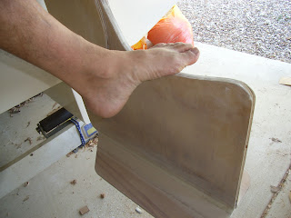
The rudder is very robust, and the endplate is glued on with epoxy and is supported by a substantial epoxy fillet reinforced by 450GSM woven glass. This should be strong enough to act as a step to assist people re-entering from the water.

I also shaped the upper edge of the rudder so that a foot can be placed on it without sliding off. The combination of the endplate, top of the rudder, and the outboard motor well should make for a serviceable ladder.

This shows the tiller position looking aft towards the rear bulkhead.


Here you can see the leather chaffing guard sewn around the mast where it enters the partner.

This is leathering on the yard at the point where the halyard is attached. The lump in the middle is the leather sewn around a commercial fairlead.

Here you can see leather glued to the started side of the boom, which in this view is upside down. The downhaul is attached through the black cleat and pulls downwards when the boat is rigged.

This is a pulley block with beckett attached to a pad eye which has been very securely screwed to the masthead. The mast is square sectioned and solid Hoop Pine.
Once the boat has been launched and initial test sailing has been conducted, I will publish another post.
Read More..

Didi 29 Retro Progress

Bruce Mierke is building a Didi 29 Retro in Murphy, North Carolina. Bruce is a professional boatbuilder, building her for himself and progressing nicely. He has now completed the hull and it will be turned over in a few weeks.

This design is based on the Didi 26, modified to create a more classic image. Carrying a choice of rigs, the squaretop Marconi rig below and two gaff rigs further down the page. It is a radius chine plywood design, round bilge from plywood and can be built from plans or a CNC kit. Although Bruce is a professional builder, I developed this construction method primarily for amateurs and they have built many boats to this range of designs.
Marconi rig of Didi 29 Retro
Here are the latest photos from Bruce, showing the beautiful standard of finish that he has achieved.
Beautiful hull finish.
Two gaff rigs, racing at left and cruising at right.

For more info on this and our other designs, visit http://dixdesign.com/
Read More..